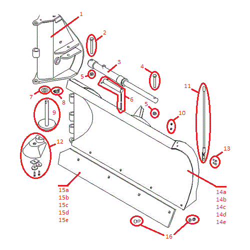
Boss Rt3 V Blade Wiring Diagram
We carry only Boss OEM Parts so you can rest assure you are getting Boss Original Snow. Is the least efficient diagram among the electrical wiring diagram.
 Boss Rt3 Wiring Harness Diagram Chevy Trane Air Handler Wiring Schematics Begeboy Wiring Diagram Source
Trip Blade Boss Rt3 Wiring Diagram It is far more helpful as a reference guide if anyone wants to know about the homes electrical system.

Boss rt3 v blade wiring diagram. This manual is used for the installation of all V-Plows. Lay each blade half flat on the box top face down. Snow Plow Parts Salt Spreader Parts.
RT3 Wiring Diagram G10002 73A 73A 73B 73 Straight Blade Manifold HYD07045 See Figure 12. DXT RT3 10 with SmartHitch2. RT3 Straight Blade Wiring Diagram Figure 5.
Reserves the right under its continuous product improvement policy to change. Straight Blade RT3 Harness Wiring Diagram. Rt3 V-Blade Manifold Wiring Diagram SmartHitch 2 Wiring Diagram Figure 27.
Wiring Diagram Sheets Detail. Mobile - View Full Site. Wiring Diagram SmartLight2 Wiring Schematic SmartLight2 Control Plug Pin Functions.
8272004 95947 PM. Electrical System Wiring Schematic Truck Side Electrical System Wiring Schematic Truck Side G10272. Align the center bushings on Left Blade Half 5 with the center bushings on Right Blade Half 4.
Its components are shown by the pictorial to be easily identifiable. Reserves the right under its continuous product improvement policy to. Cart 0 About Us.
We carry a big inventory of Boss Snow Plow Parts so your repair parts will ship out fast. Snowplow Assembly Installation Procedure. Its components are shown by the pictorial to be easily identifiable.
It shows the elements of the circuit as streamlined forms as well as the power and signal links between the devices. The BOSS Straight Blade RT3 with Smart Hitch 2 Parts Diagram is the best way to find the straight blade motor kit headlight and controller parts. Welcome To Boss Parts Depot If You Have Any Questions Dont Hesistate to Call Us.
RT3 Power-V Blade with SmartHitch Wiring Diagram Figure 5. Reserves the right under its continuous product improvement policy to. Position CHA09716 Center Section 2 on top of both blades so that all.
RT3 Straight Blade Wiring Diagram 9 Figure 7. A wiring diagram is a simplified standard photographic depiction of an electrical circuit. Buy Boss Snow Plow Power-V RT3 with SmartHitch2 Parts by Part Look-Up Diagram.
The boss snow plow wiring diagram Simple Wiring Diagram For Boss Snow Plow Boss Plow Wiring Diagram V Boss V Plow Wire Harness Installation Boss Snow Plow Wiring Harness. Remove Left Blade Half 5 and Right Blade Half 4 from the crate. Electrical System Wiring Schematic Plow Side G10271.
Stand blade assembly upright with blade halves in the V position. BOSS Products MJ. RT3 10 with SmartHitch.
Collection of boss v plow wiring diagram. BOSS PRODUCTS reserves the right under its continuous product improvement policy to change construction or design details and furnish equipment when so altered without reference to illustrations or specifications used herein. BOSS Products MJ.
RT3 POWER-V BLADE WITH SMART HITCH. Boss RT3 Wiring Harness 13 Pin. RT3 Power-V Blade wSmartHitch2 Installation Manual Serial 103272 higher RT3 Power-V Blade wSmartHitch2 Installation Manual RT3 Power-V Blade wSmartHitch2 Installation Manual Serial 400000000 Higher.
The general process for all V-PlowBoss RT3 with SmartHitch 2 Wiring Harness. DXT RT3 with SmartHitch2. Blade Half 5 passenger side Blade Half 4 and Center Section 2 hinge bushings.
Is the least efficient diagram among the electrical wiring diagram. HYD07044 with SmartHitch2 Wiring Diagram G10445 Wire Color Wire Function Green Right Wing In Right Wing Out White Lift Orange Lower RedBlack Left Wing In Blue Left Wing Out Black SmartHitch2 12V WhiteBlack Pump Solenoid Brown Ground. RT3 V-Blade Manifold Wiring Diagram 20.
Boss Snow Plow Power-V Parts Boss Power V-XT and Municipal Power-V Plow Parts Diagram. IMPORTANT COVID-19 UPDATE PLEASE VIEW THE FOLLOWING INFORMATION BEFORE ORDERING. Part Lookup Tool PARTS PLOWS.
Hydraulic Power Unit Fill Procedure 8. Microsoft Word - 13-pin Wiring Schematicdoc Author. RT3 Wiring Diagram G10002 Straight Blade Manifold HYD07045 See Figure 4.
10 RT3 Straight Blade Wiring Schematic Figure 6. BOSS Products MJ. BOSS PRODUCTS reserves the right under its continuous product improvement policy to change construction or design details and furnish equipment when so altered without reference to illustrations or specifications used herein.
Boss Rt3 Straight Blade Wiring Diagram It is far more helpful as a reference guide if anyone wants to know about the homes electrical system. RT3 Straight Blade Manifold Wiring Diagrams. Secure Center Hinge Pin 11 through the forward hole on Center Section 2 using one 38-16 X 1-14 Hex Head Cap Screw w Nylon Lock Patch 46 and one 38 Split Lock Washer 64.
 Boss Snowplow Parts Diagrams From Iteparts Com
 Aftermarket Boss Rt3 V Plow Horizontal Hinge Threaded Pin Kit Msc09649 Plowpartsonline
 Power V Rt3 Blade Half Left Parts Diagram Shop Iteparts Com
Https Encrypted Tbn0 Gstatic Com Images Q Tbn And9gcqzqvlv0gvfbeqqopezrmkyoxw7wcrpsxmdgvpvkliffhx2yfsy Usqp Cau
 Western Plow Part 65800 Battery Tray Ms Tray Westerns Battery
